
Mohammed Shabaj Ahmed
Embedded Software Engineer
Two Wheel Self-Balancing Robot
2019-08-14
This instructable will go through the design and build process for a self-balancing robot.
As a note, I just want to say that self-balancing robots are not a new concept and they have been built and documented by others. I want to use this opportunity to share with you my interpretation of this robot.
What is a self-balancing robot?
A self-balancing robot is a system that uses inertial measurement data, gathered from an onboard sensor, to continuously adjust its position to keep upright.
How does it work?
A simple analogy to consider is an inverted pendulum, where the centre of mass is above the pivot point. However, in our case, we are restricting the pendulum to one degree of freedom by having one axis of rotation—the axis of the two wheels.
Since any disturbance will cause the robot to fall, we need a method of actively keeping it balanced. This is where our closed-loop algorithm (PID controller) comes into play. Knowing which direction our robot is falling, we can adjust the direction of rotation of our motors to keep the system balanced.
How does the closed-loop algorithm work?
The basic principle is: if the robot is falling forward, it will compensate by moving forward to catch itself; if falling backward, it will move backward.
So, we need to do two things:
- Calculate the angle of inclination (Roll).
- Control the motor direction accordingly.
How will we measure the angle of inclination?
We'll use an Inertial Measurement Unit (IMU), specifically the MPU-6050, which includes:
- Accelerometer: measures proper acceleration.
- Gyroscope: measures angular velocity.
Sensor drawbacks:
- The accelerometer is noisy but consistent over time.
- The gyroscope drifts over time but is initially accurate.
For this instructable, we'll use the onboard Digital Motion Processing (DMP) of the MPU-6050. Others may use a complementary filter—either works.
Supplies
Parts:
- Arduino Pro Mini 3.3V 8MHz (ATmega328)
- FT232RL USB to TTL Serial Adapter (3.3V–5.5V)
- GY-521 module with MPU-6050
- 2x N20 Micro Gear Motors (6V, 300rpm)
- L298N Motor Driver
- LM2596S DC to DC Buck Converter
- 9.7V Li-ion Rechargeable Battery Pack
- Battery Strap
- 2x Prototyping PCB Boards
- Male & Female Header Pins
- Jumper Wires
Tools:
- Soldering Iron & Solder
- Nylon Hex Spacer Standoff
- Precision Screwdriver Set
- 3D Printer
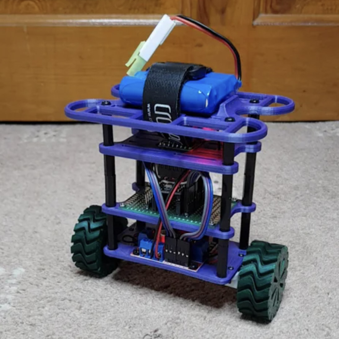
Step 1: Construction
I 3D printed the chassis and used standoffs to assemble the robot, which consists of 4 layers:
- Bottom Layer: Mounts motors and L298N motor driver.
- Second Layer: Holds the prototype board with Arduino and headers.
- Third Layer: Mounts the IMU.
- Top ("Bumper") Layer: Holds battery, buck converter, and switch.
Design Principle: Keep everything modular for easy replacement and reusability.
Download the STL files and code from GitHub.
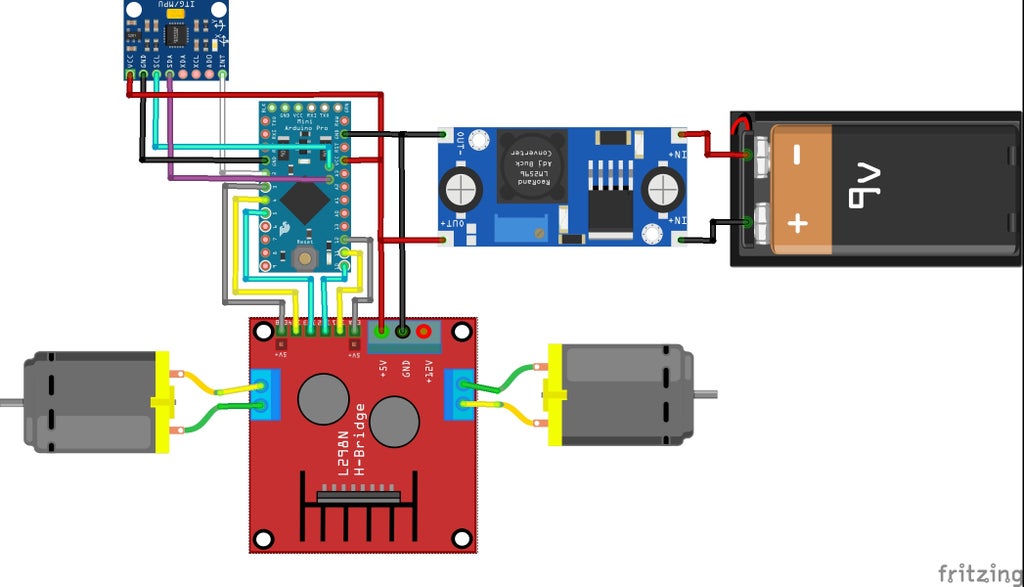
Step 2: Wiring
I soldered female headers to the perf-board to match the Arduino. Then I soldered male headers for I/O access. Components were mounted to the 3D printed frame and connected via jumper wires.
Step 3: Control Theory
To balance the robot, we use a PID controller:
- Proportional (P): Output is proportional to error.
- Integral (I): Accumulates error over time to reduce steady-state error.
- Derivative (D): Predicts future error based on rate of change, reducing oscillation.
Algorithm Summary:
- Calculate angle of inclination (error).
- Compute control signal:
P + I + D. - Send control signal to motors.
- Large error = fast motor response.
Small error = slow motor adjustment.
Step 4: Using MPU-6050
MPU6050 Library
Calibrating Offsets
Use this calibration script by Luis Rodenas to calculate and set offset values in setup().
Digital Motion Processor (DMP)
What is DMP?
An onboard processor that fuses motion data from the gyroscope and accelerometer.How to use DMP?
Use the example sketch:File → Examples → MPU6050 → MPU6050_DMP6
Step 5: Coding
I used Arduino IDE and FTDI adapter to program the Arduino Pro Mini.
Base code: MPU6050_DMP6 example sketch
Additions: PID() and MotorDriver() functions
Required Libraries:
Wire.hMPU6050I2Cdev.h
Pseudo Code
// Include Libraries
#include <Wire.h>
#include <I2Cdev.h>
#include <MPU6050.h>

// Initialise variables and objects

void setup() {
  // Set pinModes for motors and LED
  // Initialise MPU6050 and set offsets
}

void PID() {
  // Calculate PID output
}

void MotorDriver(float pid_output) {
  // Drive motors using PID result
}

void loop() {
  // Get data from DMP
  PID();
  MotorDriver();
}
The full source code is available onGitHub
Step 6: PID Tuning Procedure
- Set I and D to 0.
- Increase P until robot starts oscillating.
- Increase I to accelerate correction.
- Add D to reduce oscillations.
If tuning fails, start over with a new P value. Each system may need vastly different PID values.
Step 7: Conclusion
The motors were too slow to respond to disturbances, and the system lacked inertia. As a result, the robot would lean and roll instead of balancing. The 3D printed wheels lacked traction and would slip.
Suggestions for Improvement:
- Use aster, higher-torque motors
- Add weight higher up (or use heavier batteries)
- Replace 3D-printed wheels with rubber onesfor better traction